Sysquake Pro – Table of Contents
Sysquake for LaTeX – Table of Contents
PID_ct.sq
Continuous-time PID controller
PID controllers, or proportional-integral-derivative controllers, are
probably the most popular kind of linear single-input single-output
controllers. This is justified by their simplicity and their effectiveness
for a large class of systems. Taking as input the difference between the
desired set-point
- a proportional term (the larger the error, the larger the control signal to reduce it);
- an integral term (if a nonzero control signal is required to cancel out the error, the control signal is increased until the error vanishes);
- a derivative term (the evolution of the error is anticipated to increase damping).
Weights can be specified either separately for the three terms, or as
a global gain

The transfer function of the controller
![]()
Translating the conceptual simplicity of the PID into an effective design
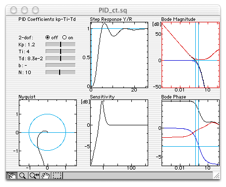
is not always straightforward. PID_ct.sq displays the graphics where common
specifications can be checked

For set-point tracking, filtering the same way the measured output and
the set-point by considering only the error
![]()
Figures
The figures are the same as those defined for RST_ct.sq, except for the Open-Loop Zeros and Poles and the Closed-Loop Poles which are not defined.
Settings
The System, Sampling Period, method for converting to digital controller, and Damping Specification have the same effect as the corresponding menu entries defined in RST_ct.sq. Two new entries are defined.
PID Coefficients
The three parameters of the PID (
No Derivator On Reference
When the input of the PID controller is the error between the set-point and the measured output, discontinuities of the set-point are differentiated by the derivator component of the PID and yield infinite values for the control signal (see above).
When No Derivator On Reference is checked, the set-point is not differentiated.
Display Frequency Line
When selected, moving the mouse above a frequency response (Bode or sensitivity) will display a corresponding line in other frequency responses, Nyquist diagrams, and zero/pole diagrams.