Design of a PD controller with Sysquake
Sysquake lets you design quickly and easily good controllers and by helping you to understand what you are doing. As an example, here is how to design a digital PD controller (a kind of PID controller) in the root locus.
Position control of an electrical drive is considered. The transfer function of the system sampled at Ts = 0.025 s is
![]()
The controlled system should have no steady-state error, an absolute damping factor of 1/20 in 5 samples, and a relative damping of 1/535 per oscillation.
Design of a proportional controller
Let us use PID_dt.sq, an application provided with Sysquake for the design of discrete-time PID controllers. First, we enter the model of the system as two polynomials (numerator and denominator of a discrete-time transfer function) by selecting the menu Settings/System (discrete-time model):
[1.23e-3, 1.21e-3], poly([1, 0.95])
The numerator is entered as the vector of its coefficients, while the denominator is calculated with the poly function which takes the roots of the polynomial as argument. Note that we could also have entered the continuous-time model and let Sysquake convert it to a discrete-time model using a sampler and a zero-order hold.
What about the specifications? With an integrator in the system (the pole at 1), there is no steady-state error. The absolute damping of 1/20 in 5 samples corresponds to (1/20)^(1/5) per sample. We can type this expression directly in the command window of Sysquake:

So the absolute damping should be at least a factor 0.55 per sample. The relative damping is usually expressed with the zeta parameter, which can be calculated with
![]()
where lambda is the damping between two successive oscillations. We use Sysquake again to obtain zeta = 0.707. These two values can be entered in the dialog box which is displayed with the menu entry Settings/Damping Specifications.
The PID controller still has the default values, which are not appropriate. Let us replace it with the proportional controller K(z) = 10.2. In the Settings menu, we select PID Coefficients and enter
10.2, [], []
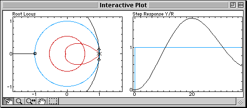
The brackets specify empty matrices which are placeholders for the unused derivator and integrator terms. The following root locus and step response are obtained:

On the left, the figure shows the root locus in black, the closed-loop poles which move along the branches of the root locus as the gain of the controller changes (triangles), and the specifications in red (the circle corresponds to the absolute damping, and the smaller region to the relative damping). Clearly, the damping requirements cannot be achieved for any value of the gain, because the branches of the root locus don't even enter into the permitted region. We can also observe that the step response (right) is damped very slowly.
Proportional-Derivative Controller
A derivative term is added to the controller to modify the root locus (the derivative term is known to have the effect of adding damping). The controller is now
![]()
where Kp is the controller gain and Td the constant of the derivator. We select Settings/PID Coefficients and enter
10.2, [], 0.05
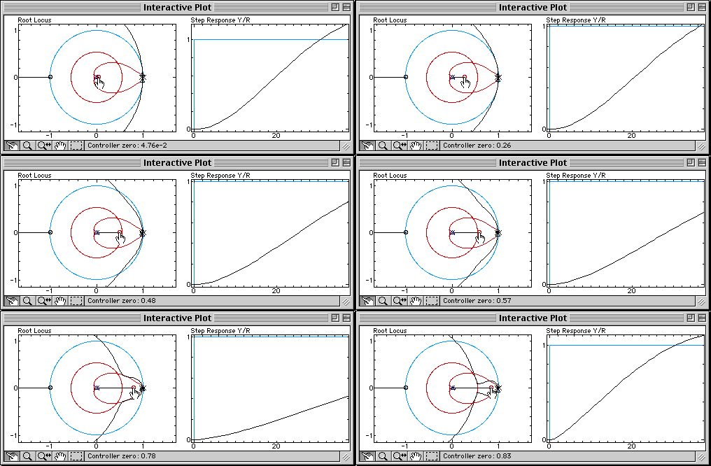
A pole (blue cross) and a zero (red circle) are added to the controller. Since the root locus is still very far from the permitted damping region, let us move the zero of the controller to the right, and observe what happens:

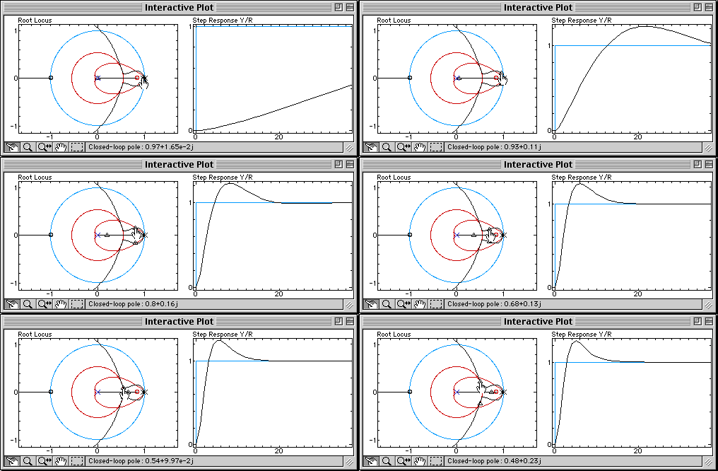
The branches of the root locus are bent toward the zero brought by the derivative term. The bending is increased when the zero is moved, until damping specifications can be fulfilled (at that time, Td = 0.12). The appropriate proportional gain can then be found by moving the closed-loop poles on the branches:

Sysquake Pro and Sysquake come with this discrete-time PID application. With them, you can:
- manipulate graphics yourself the way you want, with much smoother results;
- choose other parameters, e.g. to use the model of your own systems or to remove the derivator effect on the set-point;
- observe other quantities, such as the Nyquist diagram or sensitivities which enable to obtain easily good robustness;
- use features such as multi-level undo, printing, EPS output (Sysquake only), etc.
- study the algorithms used in the PID design application by reading the source code, and modify it;
- load other applications in domains such as automatic control, signal processing, physics, demography, etc.
- develop your own applications by writing script files.
You can download now Sysquake, which includes this controller design example.