Disponible uniquement en anglais
Sysquake Pro – Table of Contents
Sysquake for LaTeX – Table of Contents
relay.sq
Relay controller
A relay with hysteresis is used as a controller. The hysteresis prevents the system to oscillate at high frequency.

First contact
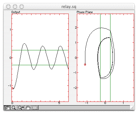
A second-order system is controlled by relay with hysteresis. A null set-point
is assumed. The left figure shows the time response (starting with null initial
conditions and the relay in the high level); the right figure shows the
phase plane
Figures
Output
The system output is displayed in black, and the hysteresis level of the relay as green horizontal lines. The hysteresis level can be manipulated.
Input
The system input (output of the relay with the opposite sign) is displayed in black.
Phase Plane
The system output is displayed in black in the phase plane; the horizontal axis is the output, and the vertical axis its derivative. The hysteresis level is displayed as green lines and can be manipulated.
Nyquist
The Nyquist diagram of the system is displayed in black, and
Settings
System
The system can be edited in a dialog box. It is given by the numerator and denominator of a continuous-time transfer function.
Hysteresis
The hysteresis level can be edited in a dialog box.